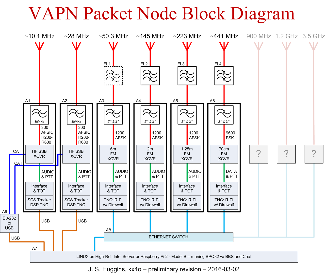
The block diagram for the preliminary design continues its evolution. The outlines of the notional radio system assemblies are now nice thick black lines making it obvious what goes inside. Reference letters, i.e. A1, A2, etc., are now part of the drawing as design continues per Y14.44-2008.
Low-pass filters within the radio system enclosure
The big change is placing the LPF filters within the radio system assemblies. I always intended to include them inside this enclosure, but only caught the mistake today. The actual filters are small enough to easily fit within a 2U or 3U rack enclosure although the two HF LPFs might require a slightly deeper rack box.
Nice thing about block diagrams… fixing mistakes is much easier now than after the thing is built.
Summary of changes
- Overall formatting change resulting in a slightly better looking web-ready graphic;
- Moved all low-pass filter components within the radio system assemblies;
- Annotated radio system assemblies A1, A2, A3, A4, A5 and A6;
- Annotated cavity filters FL1, FL2, FL3 and FL4;
- Annotated switch and node assemblies A7, A8 and A9;
- Grayed out all nomenclature concerning the 900MHz and above components – I just want a place holder for now;
- Removed some of the extraneous detail around the main server box at the bottom such as “PANEL CONNECTORS” as this is kind of obvious to anyone trained enough to follow this drawing;
PDF available here 2016-03-02_VAPN_System_Line_Drawing.